MikroTik Dual WAN PCC Load Balancing with PPPoE Server
Hi geek, you are here because you are finding a complete MikroTik Dual WAN PCC Load balancing and Link Redundancy solution with PPPoE Server because you have managed two ISP connections and want to provide an uninterrupted internet connection to your clients. You also want to manage your LAN clients with PPPoE Server because it provides a hassle free network administration.
MikroTik PCC provides 100% reliable Load Balancing and Link Redundancy network and in my previous article I discussed how MikroTik PCC work and how to configure a basic MikroTik PCC Load Balancing and Link Redundancy network. In this article I will show how to configure a complete Dual WAN PCC Load Balancing and Link Redundancy network with MikroTik PPPoE Server.
Core Devices and IP Information
To configure a PCC load balancing and link redundancy network with PPPoE Server, I am using MikroTik RouterOS v6.38.1 which has two ISP connections available. IP information that I am using for this network configuration are given below.
- ISP1 IP 192.168.30.2/30 and Gateway IP 192.168.30.1
- ISP2 IP 192.168.60.2/30 and Gateway IP 192.168.60.1
- LAN network: 10.10.70.0/24 and LAN Gateway IP 10.10.70.1/24
- DNS IP: 8.8.8.8 and 8.8.4.4
This IP information is just for my RND purpose. Change this information according to your network requirements.
Network Diagram
To configure a Load Balancing and Link Redundancy network with MikroTik RouterOS, I am following a network diagram like below image.
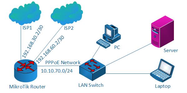
In this network, MikroTik Router’s 1st Interface (ether1) is connected to ISP1 having IP Address 192.168.30.2/30 and 2nd Interface (ether2) is connected to ISP2 having IP Address 192.168.60.2/30. In real network these IP Addresses should replace with your ISP given public IP Address. Again, 3rd Interface (ether3) is our LAN interface where PPPoE server will be installed and PPPoE network will be 10.10.70.0/24.
We will configure Dual WAN PCC Load Balancing and Link Redundancy in this MikroTik Router and after PCC configuration MikroTik will pass LAN traffic through both ISP equally and if any ISP is disconnected, other ISP will be used to pass all traffic until the disconnected ISP becomes alive. If disconnected ISP becomes alive, both ISP will be used to pass LAN traffic again automatically.
MikroTik PCC Load Balancing Configuration with PPPoE Server
We will now configure PCC Load Balancing network with PPPoE Server according to our above network diagram. Complete configuration can be divided into two parts.
- MikroTik PCC load balancing configuration over DUAL WAN
- PPPoE server configuration for LAN
Part 1: MikroTik PCC Load Balancing Configuration over DUAL WAN
In first part, we will do PCC Load Balancing and Link Redundancy configuration. Complete PCC load balancing configuration includes assigning WAN IP, creating mangle rule, policy based routing configuration and NAT configuration. We will now perform these tasks in our MikroTik Router.
Assigning WAN IP
We have two WAN IPs given from ISP1 and ISP2. We will now assign this WAN IPs in our MikroTik Router’s WAN interface. The following steps will show how to assign WAN IP in your MikroTik Router.
- Login to MikroTik Router with winbox (with admin privilege credential).
- Click on Interfaces menu item. Interface List window will appear.
- Double click on ether1 interface and rename it as ISP1 and then click Apply and OK button. Similarly, click on ether2 interface and rename it as ISP2 and then click Apply and OK button. Again, click on ether3 interface and rename it as LAN and then click Apply and OK button.
- Go to IP > Addresses menu item and click on PLUS SIGN (+). In New Address window, put ISP1 IP address (192.168.30.2/30) in Address input field and choose ISP1 from Interface dropdown menu and then click on Apply and OK button.
- Similarly, click on PLUS SIGN (+). In New Address window, put ISP2 IP address (192.168.60.2/30) in Address input field and choose ISP2 from Interface dropdown menu and then click on Apply and OK button.
Alternatively, you can run below command from MikroTik CLI.
/interfaceset “ether1″ name=”ISP1”
set “ether2″ name=”ISP2”
set “ether3″ name=”LAN”
/ ip address
add address=192.168.30.2/30 interface=ISP1
add address=192.168.60.2/30 interface=ISP2
Assigning WAN IP in MikroTik Router has been completed. Now we will create Mangle rule to mark connection and routing.
Creating Mangle Rule
Mangle rule is used to mark packet for proper routing. In this part we will create various mangle rules that will help to mark connection and routing and pass different network traffics to different WAN connections. Go to IP > Firewall menu item and click on Mangle tab and create the following 10 rules as indicated.
- Click on PLUS SIGN (+). New Mangle Rule window will appear. Click on General tab and choose prerouting from Chain dropdown menu and put ISP1 network address (192.168.30.0/30) in Dst. Address input and then choose LAN from In. Interface dropdown menu. Now click on Action tab and choose accept from Action dropdown menu and then click on Apply and OK button.
- Click on PLUS SIGN (+). New Mangle Rule window will appear. Click on General tab and choose prerouting from Chain dropdown menu and put ISP2 network address (192.168.60.0/30) in Dst. Address input and then choose LAN from In. Interface dropdown menu. Now click on Action tab and choose accept from Action dropdown menu and then click on Apply and OK button.
- Click on PLUS SIGN (+). New Mangle Rule window will appear. Click on General tab and choose prerouting from Chain dropdown menu and choose ISP1 from In. Interface dropdown menu and then choose no-mark from Connection Mark dropdown menu. Now click on Action tab and choose mark connection from Action dropdown menu and put a connection mark name (ISP1_conn) in New Connection Mark input field. Uncheck Passthrough checkbox if it is checked. Click on Apply and OK button.
- Click on PLUS SIGN (+). New Mangle Rule window will appear. Click on General tab and choose prerouting from Chain dropdown menu and choose ISP2 from In. Interface dropdown menu and then choose no-mark from Connection Mark dropdown menu. Now click on Action tab and choose mark connection from Action dropdown menu and put a connection mark name (ISP2_conn) in New Connection Mark input field. Uncheck Passthrough checkbox if it is checked. Click on Apply and OK button.
- Click on PLUS SIGN (+). New Mangle Rule window will appear. Click on General tab and choose prerouting from Chain dropdown menu and choose LAN from In. Interface dropdown menu and then choose no-mark from Connection Mark dropdown menu. Click on Advanced tab and choose both addresses from Per Connection Classifier dropdown menu and put 2 in next 1st input field and 0 in 2nd input field. Click on Extra tab and click on Dst. Address Type option and choose local from Address Type dropdown menu and then click on Invert checkbox. Click on Action tab and choose mark connection from Action dropdown menu and put a connection mark name (ISP1_conn) in New Connection Mark input field. Uncheck Passthrough checkbox if it is checked. Click on Apply and OK button.
- Click on PLUS SIGN (+). New Mangle Rule window will appear. Click on General tab and choose prerouting from Chain dropdown menu and choose LAN from In. Interface dropdown menu and then choose no-mark from Connection Mark dropdown menu. Click on Advanced tab and choose both addresses from Per Connection Classifier dropdown menu and put 2 in next 1st input field and 1 in 2nd input field. Click on Extra tab and click on Dst. Address Type option and choose local from Address Type dropdown menu and then click on Invert checkbox. Click on Action tab and choose mark connection from Action dropdown menu and put a connection mark name (ISP2_conn) in New Connection Mark input field. Uncheck Passthrough checkbox if it is checked. Click on Apply and OK button.
- Click on PLUS SIGN (+). New Mangle Rule window will appear. Click on General tab and choose prerouting from Chain dropdown menu and choose LAN from In. Interface dropdown menu and then choose ISP1_conn from Connection Mark dropdown menu. Now click on Action tab and choose mark routing from Action dropdown menu and put a routing mark name (to_ISP1) in New Routing Mark input field. Uncheck Passthrough checkbox if it is checked. Click on Apply and OK button.
- Click on PLUS SIGN (+). New Mangle Rule window will appear. Click on General tab and choose prerouting from Chain dropdown menu and choose LAN from In. Interface dropdown menu and then choose ISP2_conn from Connection Mark dropdown menu. Now click on Action tab and choose mark routing from Action dropdown menu and put a routing mark name (to_ISP2) in New Routing Mark input field. Uncheck Passthrough checkbox if it is checked. Click on Apply and OK button.
- Click on PLUS SIGN (+). New Mangle Rule window will appear. Click on General tab and choose output from Chain dropdown menu and then choose ISP1_conn from Connection Mark dropdown menu. Now click on Action tab and choose mark routing from Action dropdown menu and put a routing mark name (to_ISP1) in New Routing Mark input field. Uncheck Passthrough checkbox if it is checked. Click on Apply and OK button.
- Click on PLUS SIGN (+). New Mangle Rule window will appear. Click on General tab and choose output from Chain dropdown menu and then choose ISP2_conn from Connection Mark dropdown menu. Now click on Action tab and choose mark routing from Action dropdown menu and put a routing mark name (to_ISP2) in New Routing Mark input field. Uncheck Passthrough checkbox if it is checked. Click on Apply and OK button.
Alternatively, you can run below command from MikroTik CLI.
/ ip firewall mangleadd chain=prerouting dst-address=192.168.30.0/30 action=accept in-interface=LAN
add chain=prerouting dst-address=192.168.60.0/30 action=accept in-interface=LAN
add chain=prerouting in-interface=ISP1 connection-mark=no-mark action=mark-connection \
new-connection-mark=ISP1_conn
add chain=prerouting in-interface=ISP2 connection-mark=no-mark action=mark-connection \
new-connection-mark=ISP2_conn
add chain=prerouting in-interface=LAN connection-mark=no-mark dst-address-type=!local \
per-connection-classifier=both-addresses:2/0 action=mark-connection new-connection-mark=ISP1_conn
add chain=prerouting in-interface=LAN connection-mark=no-mark dst-address-type=!local \
per-connection-classifier=both-addresses:2/1 action=mark-connection new-connection-mark=ISP2_conn
add chain=prerouting connection-mark=ISP1_conn in-interface=LAN action=mark-routing \
new-routing-mark=to_ISP1
add chain=prerouting connection-mark=ISP2_conn in-interface=LAN action=mark-routing \
new-routing-mark=to_ISP2
add chain=output connection-mark=ISP1_conn action=mark-routing new-routing-mark=to_ISP1
add chain=output connection-mark=ISP2_conn action=mark-routing new-routing-mark=to_ISP2
Your Mangle list window looks like below image.
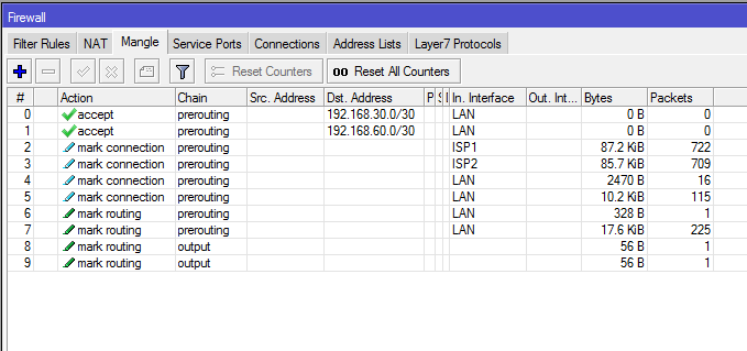
Mangle rules for matching and marking packets has been created successfully. Now we will configure policy based routing so that marked packet can be routed properly through appropriate ISP connection.
Policy Based Routing Configuration
Mangle rules that we have created will mark connection but do not do anything in routing. To pass marked connection to appropriate ISP connection, we need to configure policy based routing. The following steps will show how to configure policy based routing for the marked connection.
- Go to IP > Routes menu item. Route List window will appear.
- Click on PLUS SIGN (+). New Route window will appear. Put ISP1 gateway address (192.168.30.1) in Gateway input field. Choose ping from Check Gateway dropdown menu. Choose ISP1 routing mark (to_ISP1) from Routing Mark dropdown menu. Click Apply and OK button.
- Click on PLUS SIGN (+). New Route window will appear. Put ISP2 gateway address (192.168.60.1) in Gateway input field. Choose ping from Check Gateway dropdown menu. Choose ISP2 routing mark (to_ISP2) from Routing Mark dropdown menu. Click Apply and OK button.
- Click on PLUS SIGN (+). New Route window will appear. Put ISP1 gateway address (192.168.30.1) in Gateway input field. Choose ping from Check Gateway dropdown menu. Put 1 in Distance input field and Click Apply and OK button.
- Click on PLUS SIGN (+). New Route window will appear. Put ISP2 gateway address (192.168.60.1) in Gateway input field. Choose ping from Check Gateway dropdown menu. Put 2 in Distance input field and Click Apply and OK button.
Alternatively, you can run below command from MikroTik CLI.
/ ip routeadd dst-address=0.0.0.0/0 gateway=192.168.30.1 routing-mark=to_ISP1 check-gateway=ping
add dst-address=0.0.0.0/0 gateway=192.168.60.1 routing-mark=to_ISP2 check-gateway=ping
add dst-address=0.0.0.0/0 gateway=192.168.30.1 distance=1 check-gateway=ping
add dst-address=0.0.0.0/0 gateway=192.168.60.1 distance=2 check-gateway=ping
Your Routes window looks like the below image.
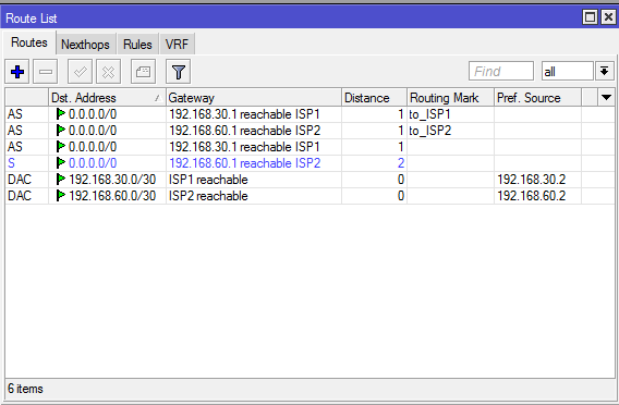
Routing configuration for selecting proper ISP has been completed. Now we need to configure NATing so that LAN traffic can reach to internet.
NAT Configuration
We will now configure NATing so that LAN user can reach to internet through MikroTik Router. The following steps will guide how to configure NAT in MikroTik Router for a specific ISP connection.
- Go to IP > Firewall menu item and click on NAT tab.
- Click on PLUS SIGN (+). New NAT Rule window will appear. In General tab, choose srcnat from Chain dropdown menu and choose ISP1 from Out. Interface dropdown menu. Click on Action tab and choose masquerade from Action dropdown menu and click Apply and OK button.
- Similarly, click on PLUS SIGN (+) again. New NAT Rule window will appear. In General tab, choose srcnat from Chain dropdown menu and choose ISP2 from Out. Interface dropdown menu. Click on Action tab and choose masquerade from Action dropdown menu and click Apply and OK button.
Alternatively, you can run below command from MikroTik CLI.
/ ip firewall natadd chain=srcnat out-interface=ISP1 action=masquerade
add chain=srcnat out-interface=ISP2 action=masquerade
NAT configuration as well as PCC Load Balancing and Link Redundancy configuration has been completed. Now we will configure PPPoE server in MikroTik Router to manage our LAN users easily.
Part 2: PPPoE Server Configuration for LAN
PPPoE provides extensive user management and network management benefits to network administrators. So it is always better to use PPPoE server for managing LAN user. Complete PPPoE Server configuration can be divided into the following four steps.
- IP Pool Configuration
- Enabling PPPoE Server
- User Profile Configuration and
- User Secrets (username and password) Configuration
IP Pool Configuration
IP Pool is IP range from where IP will be assigned to user computer after user authentication. The following steps will show how to create IP Pool in your MikroTik Router.
- Go to IP > Poolmenu item and click on PLUS SIGN (+). New IP Pool window will appear now. Put a pool name (LAN_Pool) in Name input field and address range (172.16.0.2-172.16.0.254) in Addresses input field.
- Click Applyand OK
- You can create as many IP Pools as you want following the above steps properly.
IP Pool configuration has been completed. Now we will enable PPPoE Server in MikroTik Router.
Enabling PPPoE Server
We will now enable PPPoE Server in our MikroTik Router. The following steps will show how to enable PPPoE Server in MikroTik Router.
- Click on PPPmenu item and click on PPPoE Servers tab and then click on PLUS SIGN (+). New PPPoE Service window will appear now. Put your PPPoE Server name (LAN_PPPoE_Server) in Service Name input box.
- Now choose your LAN interface (LAN) where PPPoE Server will be enabled from Interfacedrop-down menu.
- Click on One Session Per Hostif you don’t want to allow multiple session from one computer.
- At the bottom of this window, you can see four authentication methods. Select only PAP, and unselect all other options. Now click Applyand OK button.
PPPoE Server configuration in MikroTik router has been completed. Now we will create user profile so that we can apply user limitation and other user settings easily.
User Profile Configuration
User profile gives benefits to apply user settings and user limitation such as user bandwidth and number of user connection limitation. User profile also gives facility to categorize your LAN users. The following steps will show how to create user profile for your PPPoE users.
- Click on Profiles tab. You will see two default profiles are already created by MikroTik RouterOS. We will do nothing with the default profiles. Rather we will create a new profile. Click on PLUS SIGN (+). New PPP Profile window will appear now.
- Put your profile name (LAN_User_Profile) in Name input field. Now put LAN Gateway (10.10.70.1) in Local Address input field and choose your IP Pool (LAN_Pool) from Remote Address drop-down menu. Note that Local Address is the gateway address of this IP block which not included in LAN_Pool. So, when a user will be connected to this profile, he/she will get an IP from LAN_Pool and his/her gateway will be 10.10.70.1.
- At the bottom of this window, put your DNS server IP that you have got from your ISP or put Google’s public DNS 8.8.8.8 in DNS Server input box.
- Optionally, you can set bandwidth limit and number of connection limit for this profile user from Limits To set bandwidth limit, click on Limits tab and put download and upload speed in Rate Limit (rx/tx)input box in bit. For example, type 512000/512000 for this profile if you want all users of this profile get 512kbps upload and download speed. Also click on yes radio button from Only One panel. If you keep it default or no, multiple computers can be connected with same username and password. Obviously, you don’t want it.
- Now click Apply and OK button.
- You can create as many user profiles as you want following the above steps properly.
User profile configuration has been completed. Now we will create user secret (username and password) so that they can connect to our PPPoE server with this secret.
User Secret Configuration
Now we will create user secret that will be used to connect to PPPoE Server. The following steps will show how to create user secret in your MikroTik Router.
- From PPP window, click on Secretstab and then click on PLUS SIGN (+). New PPP Secret window will appear now.
- Put client username in the Nameinput box and password in Password input box. Note that username and password is necessary when any client will be connected from his workstation (PC, Laptop, Router and so on). Also, it is case-sensitive. So, be careful to put these fields.
- Now choose pppoefrom Service drop-down list and choose profile for this user (LAN_User_Profile) from Profile drop-down list.
- Optionally, you can bind any device with this username and password providing MAC address. Put MAC address of any device in Caller IDinput box. If you put MAC address of any device in Caller ID, only this device can be connected with this secret (username and password).
- You can create as many secrets as you want following the above steps.
User secret configuration has been completed as well as all the steps for configuring a PPPoE service in MikroTik router has been completed. Now it is time to show how to configure PPPoE client in any operating system.
PPPoE Client Configuration
We have completely configured PPPoE Server in MikroTik Router. Now your MikroTik is ready to accept PPPoE client. A number of PPPoE clients are present now a day. Among them, now I will show how to configure PPPoE client in windows 7 operating system. All other versions of windows operating system follow almost the same procedure. So, you don’t face any difficulty, I think. However, if you feel any problem to configure PPPoE client of any operating platform, I recommend you to go Google and search how to configure PPPoE client of that specific operating platform.
Steps to Create PPPoE dial Up Connection in Windows 7
Microsoft PC dialer is used to connect remote PPPoE Server in window 7 to get access to the internet. So, you have to configure Microsoft PC dialer in windows 7 PC to get access to the internet through your MikroTik Router. Follow my bellow steps to create PPPoE connection in windows 7 with built in PPPoE wizard.
- Connect an Ethernet cable to windows 7 PC from your network switch.
- Open Network and Sharing Centerfrom Control Panel.
- Now click on Setup a new connection or networklink under Change your networking settings area.Set Up a Connection or Network window will appear.
- In this window, click on Connect to the internetoption and click the Next Connect to the Internet window will appear.
- Click on Broadband (PPPoE)option from this window and put username and password that you have created in PPP secret configuration step in User name and Password input field accordingly. Optionally, you can change connection name in Connection name input field and you can also click on Remember this password option otherwise you have to provide password every time you start your PC. Now click on Connect If you provide correct username and password, The connection to the Internet is ready to use message will be shown. Now click on Close A dialer will be created in your windows 7 PC and you can enter your credential anytime to connect Internet with this dialer.
You are now connected to the internet with PPPoE dialer. Browse any site. I hope, you will be successful to browse any site now.
If you face any confusion to follow above steps properly, follow my video tutorial about PCC Load Balancing configuration with PPPoE Server. I hope, it will reduce your any confusion.
MikroTik Dual WAN Load Balancing with PPPoE Server has been discussed in this article. I hope you are now able to configure your Load Balancing network with PPPoE Server in MikroTik Router. However, if you face any confusion, feel free to discuss in comment or contact with me from Contact page. I will try my best to stay with you.
Why not a Cup of COFFEE if the solution?
