MikroTik IPIP Tunnel with IPsec (Site to Site VPN)
VPN (Virtual Private Network) is a technology that provides a secure tunnel across a public network. A private network user can send and receive data to any remote private network using VPN Tunnel as if his/her network device was directly connected to that private network.
MikroTik provides IPIP tunnel that is used to create a site to site VPN. IPIP tunnel is a simple protocol that encapsulates IP packets in IP to make a tunnel between two routers. To encapsulate an IP packet in another IP packet, an outer header is added mentioning the entry point of the tunnel (SourceIP) and the exit point of the tunnel (DestinationIP) but the inner packet is kept unmodified.

IPIP tunnel only encapsulates IP packets but does not provide authentication and encryption. IPIP tunnel with IPsec ensures IP packet encapsulation as well as authentication and encryption. IPsec usage makes your packets secure but it works slowly because of having extra authentication and encryption process. So, my opinion is that if data security is your concern, use IPIP tunnel with IPsec but if data security is not so headache, use only IPIP tunnel because it works so faster.
The goal of this article is to design an IPIP VPN tunnel with IPsec. So, in this article I will show how to create an IPIP tunnel with IPsec to establish a secure site to site VPN tunnel between two MikroTik Routers.
Network Diagram
To configure a site to site IPIP VPN Tunnel (with IPsec) between two MikroTik Routers, I am following a network diagram like below image.
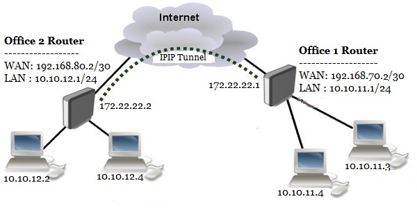
In this network, Office1 Router is connected to internet through ether1 interface having IP address 192.168.70.2/30. In your real network this IP address will be replaced with public IP address provided by your ISP. Office1 Router’s ether2 interface is connected to local network having IP network 10.10.11.0/24. After IPIP tunnel configuration, an IPIP tunnel interface will be created in Office 1 Router whose IP address will be assigned 172.22.22.1/30.
Similarly, Office2 Router is connected to internet through ether1 interface having IP address 192.168.80.2/30. In your real network this IP address will also be replaced with public IP address. Office 2 Router’s ether2 interface is connected to local network having IP network 10.10.12.0/24. After IPIP tunnel configuration an IPIP tunnel interface will also be created in Office 2 Router whose IP address will be assigned 172.22.22.2/30.
We will configure a site to site IPIP Tunnel between these two routers so that local network of these routers can communicate with each other through this VPN tunnel across public network.
Core Devices and IP Information
To configure a site to site IPIP VPN between two routers, I am using two MikroTik RouterOS v6.38.1. IP information that I am using for this network configuration are given below.
- Office 1 Router WAN IP: 192.168.70.2/30, LAN IP Block 10.10.11.0/24 and Tunnel interface IP 172.22.22.1/30
- Office 2 Router WAN IP: 192.168.80.2/30, LAN IP Block 10.10.12.0/24 and Tunnel interface IP 172.22.22.2/30
This IP information is just for my RND purpose. Change this information according to your network requirements.
Site to Site IPIP Tunnel Configuration with IPsec
We will now start our site to site IPIP VPN configuration according to the above network diagram. Complete configuration can be divided into four parts.
- MikroTik RouterOS basic configuration
- IPIP tunnel configuration with IPsec
- Assigning IP address on tunnel interface
- Static route configuration
Part 1: MikroTik RouterOS Basic Configuration
Basic RouterOS configuration includes assigning WAN IP, LAN IP, DNS IP and Route, NAT configuration. According to our network diagram, we will now complete these topics in our two MikroTik RouterOS (Office 1 Router and Office 2 Router).
Office 1 Router Basic Configuration
The following steps will guide you how to perform basic configuration in your Office 1 RouterOS.
- Login to Office 1 RouterOS using winbox and go to IP > Addresses. In Address List window, click on PLUS SIGN (+). In New Address window, put WAN IP address (192.168.70.2/30) in Address input field and choose WAN interface (ether1) from Interface dropdown menu and click on Apply and OK button. Click on PLUS SIGN again and put LAN IP (10.10.11.1/24) in Address input field and choose LAN interface (ether2) from Interface dropdown menu and click on Apply and OK button.
- Go to IP > DNS and put DNS servers IP (8.8.8.8 or 8.8.4.4) in Servers input field and click on Apply and OK button.
- Go to IP > Firewall and click on NAT tab and then click on PLUS SIGN (+). Under General tab, choose srcnat from Chain dropdown menu and click on Action tab and then choose masquerade from Action dropdown menu. Click on Apply and OK button.
- Go to IP > Routes and click on PLUS SIGN (+). In New Route window, click on Gateway input field and put WAN Gateway address (192.168.70.1) in Gateway input field and click on Apply and OK button.
Basic RouterOS configuration has been completed in Office 1 Router. Now we will do similar steps in Office 2 RouterOS.
Office 2 Router Basic Configuration
The following steps will guide you how to perform basic configuration in your Office 2 RouterOS.
- Login to Office 2 RouterOS using winbox and go to IP > Addresses. In Address List window, click on PLUS SIGN (+). In New Address window, put WAN IP address (192.168.80.2/30) in Address input field and choose WAN interface (ether1) from Interface dropdown menu and click on Apply and OK button. Click on PLUS SIGN again and put LAN IP (10.10.12.1/24) in Address input field and choose LAN interface (ether2) from Interface dropdown menu and click on Apply and OK button.
- Go to IP > DNS and put DNS servers IP (8.8.8.8 or 8.8.4.4) in Servers input field and click on Apply and OK button.
- Go to IP > Firewall and click on NAT tab and then click on PLUS SIGN (+). Under General tab, choose srcnat from Chain dropdown menu and click on Action tab and then choose masquerade from Action dropdown menu. Click on Apply and OK button.
- Go to IP > Routes and click on PLUS SIGN (+). In New Route window, click on Gateway input field and put WAN Gateway address (192.168.80.1) in Gateway input field and click on Apply and OK button.
Basic RouterOS configuration has been completed in Office 2 Router. Now we are going to start IPIP tunnel configuration.
Part 2: IPIP Tunnel Configuration with IPsec
After MikroTik Router basic configuration, we will now configure IPIP tunnel with IPsec in both MikroTik RouterOS. In IPIP tunnel configuration, we will specify local and remote IP address as well as shared secret for IPsec.
IPIP Tunnel Configuration in Office 1 Router
The following steps will show how to configure IPIP tunnel in your Office 1 Router.
- Click on Interfaces menu item from Winbox and click on IPIP Tunnel tab and then click on PLUS SIGN (+). New Interface window will appear.
- Put a meaningful IPIP tunnel interface name (ipi-tunnel-r1) in Name input field.
- Put Office 1 Router’s WAN IP address (192.168.70.2) in Local Address input field.
- Put Office 2 Router’s WAN IP address (192.168.80.2) in Remote Address input field.
- Put IPsec shared secret in IPsec Secret input field if your router supports IPsec and you wish to enable IPsec authentication and encryption. You should remember that this IPsec Secret must be same in both routers.
- Also uncheck Allow Fast Path checkbox if it is checked and you want to enable IPsec.
- Click Apply and OK button.
- You will find a new IPIP tunnel interface followed by your given name (ipip-tunnel-r1) has been created in Interface List window.
IPIP tunnel configuration in Office 1 Router has been completed. Now we will do the similar steps in our Office 2 Router to create an IPIP tunnel interface.
IPIP Tunnel Configuration in Office 2 Router
The following steps will show how to configure IPIP tunnel in your Office 2 Router.
- Click on Interfaces menu item from Winbox and click on IPIP Tunnel tab and then click on PLUS SIGN (+). New Interface window will appear.
- Put a meaningful IPIP tunnel interface name (ipip-tunnel-r2) in Name input field.
- Put Office 2 Router’s WAN IP address (192.168.80.2) in Local Address input field.
- Put Office 1 Routers WAN IP address (192.168.70.2) in Remote Address input field.
- Put IPsec shared secret in IPsec Secret input field if your router supports IPsec and you wish to enable IPsec authentication and encryption. You should remember that this IPsec Secret must be same in both routers.
- Also uncheck Allow Fast Path checkbox if it is checked and you want to enable IPsec.
- Click Apply and OK button.
- You will find a new IPIP tunnel interface followed by your given name (ipip-tunnel-r2) has been created in Interface List window.
IPIP tunnel configuration in Office 2 Router has been completed. Now we will assign IP address in our newly created IPIP tunnel interface in our both RouterOS so that both router can communicate with each other through this VPN tunnel interface.
Part 3: Assigning IP Address in IPIP Tunnel Interface
After configuring IPIP tunnel, a new IPIP tunnel interface has been created in both routers. So, if we assign same block IP in both router’s interface, the both router will be able to communicate with each other. In this part we will now assign IP address in our newly created tunnel interface.
Assigning IP Address on Office 1 Router’s IPIP Tunnel Interface
The following steps will show how to assign IP address on Office 1 Router’s tunnel interface.
- Go to IP > Address menu item and click on PLUS SIGN (+).
- Put a new private IP Block IP (172.22.22.1/30) in Address input field.
- Choose newly created tunnel interface (ipip-tunnel-r1) from Interface drop down menu.
- Click Apply and OK button.
Assigning IP address on Office 1 Router’s tunnel interface has been completed. Similarly, we will now assign IP address on Office 2 Router’s tunnel interface.
Assigning IP Address on Office 2 Router’s IPIP Tunnel Interface
The following steps will show how to assign IP address in Office 2 Router’s tunnel interface.
- Go to IP > Address menu item and click on PLUS SIGN (+).
- Put a new private IP Block IP (172.22.22.2/30) in Address input field.
- Choose newly created tunnel interface (ipip-tunnel-r2) from Interface drop down menu.
- Click Apply and OK button.
Assigning IP address on Office 2 Router’s tunnel interface has been completed. In this stage both routers are now able to communicate with each other. But both routers’ LAN cannot communicate with each other without configuring static routing. So, in the next part we will configure static routing in our both Office Router.
Part 4: Static Route Configuration
We will now configure static route in our both Office Router so that each router’s LAN can communicate with each other through IPIP tunnel.
Static Route Configuration in Office 1 Router
The following steps will show how to configure static route in Office 1 Router.
- Go to IP > Routes and click on PLUS SIGN (+). New Route window will appear.
- In New Route window, put destination IP Block (10.10.12.0/24) in Dst. Address input field.
- Put the Gateway address (172.22.22.2) in Gateway input field.
- Click Apply and OK button.
Static route configuration in Office 1 Router has been completed. Now we will configure static route in Office 2 Router.
Static Route Configuration in Office 2 Router
The following steps will show how to configure static route in Office 2 Router.
- Go to IP > Routes and click on PLUS SIGN (+). New Route window will appear.
- In New Route window, put destination IP Block (10.10.11.0/24) in Dst. Address input field.
- Put the Gateway address (172.22.22.1) in Gateway input field.
- Click Apply and OK button.
Static route configuration in Office 2 Router has been completed. Now both router as well as its LAN can communicate with each other through IPIP tunnel across public network.
To check your configuration, do a ping request from any router or any local network machine to other local network machine. If everything is OK, your ping request will be success.
You can easily create an IPIP tunnel with IPsec if you follow the above steps properly. However, if you face any confusion to follow the above steps properly, watch the below video tutorial about MikroTik IPIP tunnel configuration with IPsec. I hope it will reduce your any confusion.
IPIP VPN Tunnel Configuration with IPsec has been explained in this article. I hope you will be able to configure IPIP tunnel with IPsec between your two office routers. However, if you face any confusion to configure IPIP tunnel in your MikroTik Router, feel free to discuss in comment or contact me from Contact page. I will try my best to stay with you.
Why not a Cup of COFFEE if the solution?
