MikroTik Site to Site VPN Configuration with IPsec
VPN (Virtual Private Network) is a technology that provides a secure and encrypted tunnel across a public network. A private network user can send and receive data to any remote private network using this VPN Tunnel as if his/her network device was directly connected to that private network.
Site to Site VPN technique establishes a secure tunnel between two routers across public network and local networks of these routers can send and receive data through this VPN tunnel. MikroTik RouterOS offers IPsec (Internet Protocol Security) VPN Service that can be used to establish a site to site VPN tunnel between two routers. IPsec is a network protocol suite that authenticates and encrypts the packets of data send over a network.
The goal of this article is to configure a site to site IPsec VPN Tunnel with MikroTik RouterOS. So, rest of this article I will show how to configure IPsec VPN between two MikroTik Routers so that an IPsec VPN Tunnel can be established between them and local networks of these routers can communicate with each other.
Network Diagram
To configure a site to site IPsec VPN Tunnel between two MikroTik Routers, I am following a network diagram like below image.
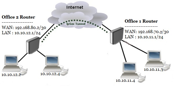
In this network, Office1 Router is connected to internet through ether1 interface having IP address 192.168.70.2/30. In your real network this IP address will be replaced with your public IP address. Office1 Router’s ether2 interface is connected to local network having IP network 10.10.11.0/24. Similarly, Office2 Router is connected to internet through ether1 interface having IP address 192.168.80.2/30. In your real network this IP address will also be replaced with public IP address. Office 2 Router’s ether2 interface is connected to local network having IP network 10.10.12.0/24. We will configure site to site IPsec VPN Tunnel between these two routers so that local network of these routers can communicate to each other through this VPN tunnel across public network.
Core Devices and IP Information
To configure a site to site IPsec VPN with MikroTik RouterOS, I am using two MikroTik RouterOS v6.38.1. IP information that I am using for this network configuration are given below.
- Office 1 Router WAN IP: 192.168.70.2/30 and LAN IP Block 10.10.11.0/24
- Office 2 Router WAN IP: 192.168.80.2/30 and LAN IP Block 10.10.12.0/24
This IP information is just for my RND purpose. Change this information according to your network requirements.
MikroTik IPsec Site to Site VPN Configuration
We will now start our site to site IPsec VPN configuration according to the above network diagram. Complete configuration can be divided into four parts.
- MikroTik RouterOS basic configuration
- IPsec Peer configuration
- IPsec Policy and Proposal Configuration
- NAT Bypass Configuration
Part 1: MikroTik RouterOS Basic Configuration
Basic RouterOS configuration includes assigning WAN IP, LAN IP, DNS IP and Route, NAT configuration. According to our network diagram, we will now complete these topics in our two MikroTik RouterOS (Office 1 Router and Office 2 Router).
Office 1 Router Basic Configuration
The following steps will guide you how to perform basic configuration in your Office 1 RouterOS.
- Login to Office 1 RouterOS using winbox and go to IP > Addresses. In Address List window, click on PLUS SIGN (+). In New Address window, put WAN IP address (192.168.70.2/30) in Address input field and choose WAN interface (ether1) from Interface dropdown menu and click on Apply and OK button. Click on PLUS SIGN again and put LAN IP (10.10.11.1/24) in Address input field and choose LAN interface (ether2) from Interface dropdown menu and click on Apply and OK button.
- Go to IP > DNS and put DNS servers IP (8.8.8.8 or 8.8.4.4) in Servers input field and click on Apply and OK button.
- Go to IP > Firewall and click on NAT tab and then click on PLUS SIGN (+). Under General tab, choose srcnat from Chain dropdown menu and click on Action tab and then choose masquerade from Action dropdown menu. Click on Apply and OK button.
- Go to IP > Routes and click on PLUS SIGN (+). In New Route window, click on Gateway input field and put WAN Gateway address (192.168.70.1) in Gateway input field and click on Apply and OK button.
Basic RouterOS configuration has been completed in Office 1 Router. Now we will do similar steps in Office 2 RouterOS.
Office 2 Router Basic Configuration
The following steps will guide you how to perform basic configuration in your Office 2 RouterOS.
- Login to Office 2 RouterOS using winbox and go to IP > Addresses. In Address List window, click on PLUS SIGN (+). In New Address window, put WAN IP address (192.168.80.2/30) in Address input field and choose WAN interface (ether1) from Interface dropdown menu and click on Apply and OK button. Click on PLUS SIGN again and put LAN IP (10.10.12.1/24) in Address input field and choose LAN interface (ether2) from Interface dropdown menu and click on Apply and OK button.
- Go to IP > DNS and put DNS servers IP (8.8.8.8 or 8.8.4.4) in Servers input field and click on Apply and OK button.
- Go to IP > Firewall and click on NAT tab and then click on PLUS SIGN (+). Under General tab, choose srcnat from Chain dropdown menu and click on Action tab and then choose masquerade from Action dropdown menu. Click on Apply and OK button.
- Go to IP > Routes and click on PLUS SIGN (+). In New Route window, click on Gateway input field and put WAN Gateway address (192.168.80.1) in Gateway input field and click on Apply and OK button.
Basic RouterOS configuration has been completed in Office 2 Router. Now we are going to start IPsec Peer configuration.
Part 2: IPsec Peer Configuration
After MikroTik Router basic configuration, we will now configure IPsec Peer in both MikroTik RouterOS. In IPsec Peer configuration, we will specify peer address, port and pre-shred-key.
IPsec Peer Configuration in Office 1 Router
The following steps will show how to configure IPsec Peer in your Office 1 RouterOS.
- Go to IP > IPsec and click on Peers tab and then click on PLUS SIGN (+).
- In New IPsec Peer window, put Office 2 Router’s WAN IP (192.168.80.2) in Address input field and put 500 in Port input field.
- Choose pre shared key option from Auth. Method dropdown menu.
- Provide a suitable password in Secret input field. This password is required for IPsec authentication and must be same in both routers.
- Click Apply and OK button.
IPsec Peer configuration in Office 1Router has been completed. Now we will configure IPsec Peer in Office 2 Router.
IPsec Peer Configuration in Office 2 Router
We will do the same steps as Office 1 Router’s IPsec Peer configuration in Office 2 Router but only address parameter will be changed.
- Go to IP > IPsec and click on Peers tab and then click on PLUS SIGN (+).
- In New IPsec Peer window, put Office 1 Router’s WAN IP (192.168.70.2) in Address input field and put 500 in Port input field.
- Choose pre shared key option from Auth. Method dropdown menu.
- Provide a suitable password in Secret input field. This password is required for IPsec authentication and must be same in both routers.
- Click Apply and OK button.
IPsec Peer configuration in our both Office Routers has been completed. Now we will start Policy and Proposal configuration for our IPsec VPN Tunnel.
Part 3: IPsec Policy and Proposal Configuration
After IPsec Peer configuration it is time to configure IPsec Policy and Proposal. It is important that proposed authentication and encryption algorithms must match on both routers. In this example, we will use predefined default proposal. You will find default proposed authentication algorithms and encryption algorithms in Proposals tab. In this part we will only configure IPsec Policy on both routers. In Policy configuration we will specify source and destination network that will pass through IPsec tunnel and the mode of this IPsec VPN.
IPsec Policy Configuration in Office 1 Router
The following steps will show how to configure IPsec Policy in Office 1 RouterOS.
- Go to IP > IPsec and click on Polices tab and then click on PLUS SIGN (+). New IPsec Policy window will appear.
- In General tab, put your source network (Office 1 Router’s network: 10.10.11.0/24) that will be matched in data packets, in Address input field and keep Src. Port untouched because we want to allow all the ports.
- Put your destination network (Office 2 Router’s network: 10.10.12.0/24) that will be matched in data packets in Address input field and keep Dst. Port untouched.
- Now click on Action tab and click on Tunnel checkbox to enable tunnel mode.
- Put Office 1 Router’s WAN IP (192.168.70.2) in SA Src. Address input field and Office 2 Router’s WAN IP (192.168.80.2) in SA Dst. Address input field.
- Make sure default option is selected in Proposal dropdown menu.
- Click Apply and OK button.
IPsec Policy configuration in Office 1 Router has been completed. Similarly we will configure IPsec Policy in Office 2 Router.
IPsec Policy Configuration in Office 1 Router
The following steps will show the configuration of IPsec Policy in Office 1 RouterOS.
- Go to IP > IPsec and click on Polices tab and then click on PLUS SIGN (+). New IPsec Policy window will appear.
- In General tab put your source network ( Office 1 Router’s network: 10.10.12.0/24) that will be matched in data packets in Address input field and keep Src. Port untouched .
- Put your destination network (Office 2 Router’s network: 10.10.11.0/24) that will be matched in packets in Address input field and keep Dst. Port untouched.
- Now click on Action tab and click on Tunnel checkbox to enable tunnel mode.
- Put Office 1 Router’s WAN IP (192.168.80.2) in SA Src. Address input field and Office 2 Router’s WAN IP (192.168.70.2) in SA Dst. Address input field.
- Make sure default option is selected in Proposal dropdown menu
- Click Apply and OK button.
IPsec Policy configuration in Office 1 Router has been completed. At this point IPsec tunnel will be created between two office routers but local networks cannot communicate with each other. This is because both routers have NAT rules that is changing source address after packet is encrypted. Remote router receives encrypted packet but is unable to decrypt it because source address do not match address specified in policy configuration. The Solution is to set up NAT Bypass rule.
Part 4: NAT Bypass Configuration
We will now configure NAT Bypass rule in our both Office Routers otherwise local network will not be able to communicate with each other.
NAT Bypass Rule Configuration in Office 1 Router
The following steps will show how to create NAT Bypass rule in your Office 1 RouterOS.
- Go to IP > Firewall and click on NAT tab and then click on PLUS SIGN (+). New NAT Rule window will appear.
- In General tab, choose srcnat from Chain dropdown menu.
- Put Office 1 Router’s LAN network (10.10.11.0/24) that wants to communicate to Office 2 Router, in Src. Address input field.
- Put Office 2 Router’s LAN network (10.10.12.0/24) where Office 1 Router wants to reach, in Dst. Address input field.
- Click on Action tab and choose accept option from Action dropdown menu.
- Click Apply and OK button.
- Your newly created rule will be available in the list table. Now place this rule at first position by drag and drop otherwise this rule will not be workable.
NAT Bypass rule in Office 1 Router has been completed. Similarly we will create NAT Bypass rule in Office 2 RouterOS.
NAT Bypass Rule Configuration in Office 1 Router
The following steps will show the configuration of NAT Bypass rule in Office2 RouterOS.
- Go to IP > Firewall and click on NAT tab and then click on PLUS SIGN (+). New NAT Rule window will appear.
- In General tab, choose srcnat from Chain dropdown menu.
- Put Office 2 Router’s LAN network (10.10.12.0/24) that wants to communicate to Office 1 Router, in Src. Address input field.
- Put Office 1 Router’s LAN network (10.10.11.0/24) where Office 2 Router wants to reach, in Dst. Address input field.
- Click on Action tab and choose accept option from Action dropdown menu.
- Click Apply and OK button.
- Your newly created rule will be available in the list table. Now place this rule at first position by drag and drop otherwise this rule will not be workable.
NAT Bypass rule in Office 2 Router has been completed. Now Office 1 Router’s local network will able to reach Office 2 Router’s local network through IPsec VPN Tunnel across public network and vice versa. To check your configuration, do a ping request from any local network machine to other local network machine. If everything is OK, your ping request will be success.
If you face any confusion to do above steps properly, watch my video about MikroTik IPsec Site to Site VPN Configuration. I hope it will reduce your any confusion.
MikroTik IPsec Site to Site VPN Configuration has been explained in this article. I hope you are now able to configure site to site IPsec VPN between two routers following the above steps properly. However, if you face any problem to configure IPsec site to site VPN, feel free to discuss in comment or contact with me from Contact page. I will try my best to stay with you.
Why not a Cup of COFFEE if the solution?

Thanks, Its work
Thanks for sharing. However what if both sites, they have dynamic WAN addresses and not static? Routers are connected to the modem/router of the internet provider through PPPoE passthrough.
Static Public IP is necessary to make site to site VPN connection. Using PPPOE connection, it is possible to get static IP. So, request your ISP to assign a static public IP for your connection.
Dear,
Thanks a lot !
It works…
So, my SITE 2 does not have Static Public IP’s. They are behind a Verizon Modem.
What is the workaround, if any?
In this case, you can use Server Client site to site VPN with PPTP method.
Hi,
I have two Mikrotik routers with a 4G connection, this works for me or not.
Thanks,
It should work.
hi,
please share the network settings in VMware workstation
Follow this article on MikroTik CHR on VMware Workstation
Hello
managed to establish the tunnel using version 6.46 stable. However nat seemed to not work. I can’t ping from mikrotik to the LAN.
Thankz
Thank you for the clear explanation. I think you forgot to change some details when you did your copy and poste for section sIPsec Policy Configuration for router 2 (it is the exact same as router 1), either that, or I did not understand the settings as well as I thought!
It was old RouterOS configuration. New version has some changes. I will try to configure in new version soon.
Raphael can I make Site to Site VPN with Dynamic DNS ?
No, you should use static public IP address.
if you could add
this is under identities
to this
Choose pre shared key option from Auth. Method dropdown menu.
this would be good