MikroTik Load Balancing with 2 PPPoE and 1 Static WAN using ECMP
ECMP provides almost 100% reliable load balancing and link redundancy solution. ECMP is a per connection load balancing where connection is marked with source and destination IP pair. In my previous article I discussed how to configure DUAL WAN load balancing with failover using ECMP method where WAN connections were static IP Addresses. But some ISP companies use PPPoE service for their client connection. So, some network administrators become confused to configure load balancing with PPPoE WAN connection because PPPoE WAN connection is a little bit complex than static WAN connection. Some of my loyal readers also ask me to make a tutorial on Load Balancing with PPPoE Client. So, in this article I will discuss how to configure Load Balancing with Failover over two PPPoE WAN connections and one static WAN connection in MikroTik Router.
Network Diagram
We will configure Multi WAN load balancing using ECMP method according to the following network diagram.

In this network, MikroTik Router’s ether1 port is connected to ISP1 with PPPoE WAN connection (username: wan1 and Password: wan1) and ether2 port is connected to ISP2 with PPPoE WAN connection (username: wan2 and Password: wan2) and ether3 port is connected ISP3 with IP block 172.25.25.0/30 and ether4 port is connected to LAN network and its IP block is 10.10.10.0/24. PC-1 and PC-2 are two LAN workstations which are connected to LAN interface through a LAN switch.
We will configure ECMP Load Balancing in this MikroTik Router so that LAN traffics can pass though these three WAN connections equally (because we assumed that all WAN links have same bandwidth).
This ECMP configuration will also ensure Link Redundancy. So, if any WAN connection gets disconnected, LAN traffic will pass through the available WAN connections until the lost WAN connection gets available.
Load Balancing Configuration over 2 PPPoE Clients and 1 Static WAN Connection
We will now start Load Balancing and Link Redundancy configuration in MikroTik Router according to the above network diagram. Complete configuration can be divided into the following six steps.
- Renaming MikroTik interface name
- Configuring PPPoE WAN connection
- Assigning static WAN and LAN IP
- Assigning DNS IP
- NATing configuration and
- ECMP Routing configuration
Step 1: Renaming MikroTik Interface Name
We will first rename interface name so that we can easily understand and remember configuration. The following steps will show how to rename MikroTik interface name.
- Login to MikroTik Router using Winbox with full permission user privilege.
- Click on Interfaces menu item. Interface List window will appear.
- Double click on ether1 interface. The properties window of the ether1 interface will appear.
- Put WAN1 in Name input field under General tab and then click Apply and OK button.
- Similarly, rename ether2 to WAN2 and ether3 to WAN3 and ether4 to LAN.
- Your Interface List window will look like the below image.

Step 2: Configuring PPPoE WAN connection
As we have two PPPoE WAN connections, we must configure MikroTik PPPoE Client on two WAN interfaces. The following steps will show how to configure PPPoE Client on MikroTik WAN interfaces.
- Click on PPP menu item. PPP window will appear. From Interface tab, click on PLUS SIGN (+) dropdown menu and then choose PPPoE Client. New Interface window will appear.
- In General tab put your PPPoE interface name (pppoe-wan1) in Name input field and then choose WAN1 interface (in this article: WAN1) from Interface dropdown menu.
- Click on Dial Out tab and put ISP1 given username (in this article: wan1) in User input field and password (in this artcle: wan1) in Password input field. Uncheck Dial On Demand, Use Peer DNS and Add Default Route checkbox if checked.
- Click Apply and OK button.
- Similarly, configure PPPoE WAN for ISP2 on WAN2 connection (with PPPoE interface name: pppoe_wan2, username: wan2 and password: wan2 and WAN interface: WAN2).

Step 3: Assigning Static WAN and LAN IP
We will now assign static WAN and LAN IP addresses on our respected interface. The following steps will show how to assign IP address on MikroTik interfaces.
- Go to IP > Addresses menu item. Address List window will appear.
- Click on PLUS SIGN (+) and put ISP3 provided IP address (in this article: 172.25.25.2/30) in Address input field.
- Choose WAN3 from Interface dropdown menu and click Apply and OK button.
- Click on PLUS SIGN (+) again and put LAN gateway IP (in this article: 10.10.10.1/24) in Address input field and choose LAN from Interface drop down menu and then click Apply and OK button
- Your Address List window will look like the below image.

Step 4: Assigning DNS IP
DNS is required to resolve domain name to IP address. Without DNS server MikroTik Router cannot resolve domain name to IP address and fail to communicate with the public domain server. The following steps will show how to assign DNS IP in MikroTik Router.
- Go to IP > DNS menu item. DNS Settings window will appear.
- Put your DNS server IP provided by your ISP or put Google public DNS Server IP 8.8.8 in Serversinput field.
- Click Apply and OK button.
Step 5: NATing Configuration
We will now create three masquerade NAT rules so that LAN users can access internet through these three WAN connections. That means, if any packet leaves via pppoe_wan1 interface, it will be NATed with pppoe_wan1 gateway IP address and similarly if any packet leaves via pppoe_wan2 interface and WAN3 interface, it will be NATed with pppoe_wan2 gateway IP address and WAN3 gateway IP address respectively. The following steps will show how to create masquerade NAT rule in MikroTik Router.
- Go to IP > Firewall menu option. Firewall window will appear.
- Click on NAT tab and then click on PLUS SIGN (+). New NAT Rule window will appear now. From General tab, choose srcnat from Chain drop-down menu and then choose PPPoE WAN1 interface (in this article: pppoe_wan1) from Out. Interface drop-down menu. Now click on Action tab and choose masquerade from Action drop-down menu and then click Apply and OK button.
- Similarly, click on PLUS SIGN (+) again and choose srcnat from Chain drop-down menu and then choose PPPoE WAN2 interface (in this article: pppoe_wan2) from Out. Interface drop-down menu. Now click on Action tab and choose masquerade from Action drop-down menu and then click Apply and OK button.
- Similarly, click on PLUS SIGN (+) again and choose srcnat from Chain drop-down menu and put LAN IP block (10.10.10.0/24) in Src. Address input field and then choose WAN3 interface (in this article: WAN3) from Out. Interface drop-down menu. Now click on Action tab and choose masquerade from Action drop-down menu and then click Apply and OK button.

Step 6: ECMP Routing Configuration
We will now configure ECMP (Equal Cost Multi-Path) gateway over three WAN links. The following steps will show how to assign ECMP gateway in MikroTik Router.
- Go to IP > Routes menu option. Route List window will appear.
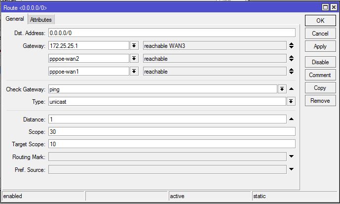
- Click on PLUS SIGN (+). New Route window will appear.
- Choose PPPoE WAN1 interface (in this article: pppoe_wan1) in Gateway drop down list and then click on Add new value button located after gateway input box. New gateway input box will appear. Choose PPPoE WAN2 gateway interface (in this article: pppoe_wan2) and click on Add new value button. Put WAN3 gateway IP (172.25.25.1) in new Gateway input box.
- Now choose ping from Check Gateway drop-down menu.
- Click Apply and OK button.
So, user’s connection will now be passed through these three WAN links successively. WAN connections will be checked by ping and if any connection gets disconnected, traffic will pass through the available WAN connections until the lost WAN connection gets connected. So, load balancing with failover will be established with ECMP load balancing method.
Connections to the Router Itself
With all multi-gateway situations there is a usual problem to reach router from public network via one, other or both gateways. Because outgoing packets use same routing decision as packets those are going through the router. So reply to a packet that was received via WAN1 might be sending out via WAN2 or WAN3. To avoid this we need to do policy based routing.
The following steps will show how to mark router’s incoming connection to pass it over proper gateway.
- Go to IP > Firewallmenu option and click on Mangle Now click on PLUS SIGN (+). New Mangle Rule window will appear now.
- From General tab, choose inputfrom Chain drop-down menu and choose PPPoE WAN1 interface (pppoe_wan1) from Interface drop-down menu. Now click on Action tab and choose mark connection from Action drop-down menu and put connection name (WAN1_CONN) whatever string you like in New Connection Mark input field and then uncheck the Passthrough check box if it is checked. Click Apply and OK button.
- Similarly, click on PLUS SIGN (+) and choose inputfrom Chain drop-down menu and then choose PPPoE WAN2 interface (pppoe_wan2) from In. Interface drop-down menu. Click on Action tab and choose mark connection from Action drop-down menu and put connection name (WAN2_CONN) whatever string you like in New Connection Mark input field and uncheck the Passthrough checkbox if it is checked and then click Apply and OK
- Similarly, click on PLUS SIGN (+) and choose inputfrom Chain drop-down menu and then choose WAN3 from In. Interface drop-down menu. Click on Action tab and choose mark connection from Action drop-down menu and put connection name (WAN3_CONN) whatever string you like in New Connection Mark input field and uncheck the Passthrough checkbox if it is checked and then click Apply and OK button.
- Now click on PLUS SIGN (+) and choose outputfrom Chain drop-down menu and then click on Connection Mark drop-down menu and choose WAN1 connection mark (in this article: WAN1_CONN) that you have created at the first step. Now click on Action tab and choose mark routing from Action drop-down menu and put routing mark name (to_WAN1) in New Routing Mark input field and uncheck the Passthrough checkbox if it is checked and then click Apply and OK button.
- Similarly, click on PLUS SIGN (+). Choose outputfrom Chain drop-down menu and choose WAN2 connection mark (in this article: WAN2_CONN) that you have created at the second step. Now click on Action tab and choose mark routing from Action drop-down menu and then put routing mark name (to_WAN2) in New Routing Mark input box and uncheck the Passthrough checkbox if it is checked. Click Apply and OK button.
- Similarly, click on PLUS SIGN (+). Choose outputfrom Chain drop-down menu and choose WAN3 connection mark (in this article: WAN3_CONN) that you have created at the third step. Now click on Action tab and choose mark routing from Action drop-down menu and then put routing mark name (to_WAN3) in New Routing Mark input box and uncheck the Passthrough checkbox if it is checked. Click Apply and OK button.

We have created policy to pass router’s incoming packets to the respected WAN interface. Now we will create routing based on this policy.
- Go to IP > Routesmenu option. Route List window will appear.
- Click on PLUS SIGN (+) and put PPPoE WAN1 gateway (pppoe_wan1) in Gatewayinput box and choose ping from Check Gateway drop down menu and then choose WAN1 routing mark (in this article: to_WAN1) from Routing Mark drop-down menu. Click Apply and OK button.
- Similarly, click on PLUS SIGN (+) and put PPPoE WAN2 gateway (pppoe_wan2) in Gatewayinput box and choose ping from Check Gateway drop down menu and then choose WAN2 routing mark (in this article: to_WAN2) from Routing Mark drop-down menu. Now click Apply and OK button.
- Similarly, click on PLUS SIGN (+) and put ISP3 gateway IP (172.25.25.1) in Gatewayinput box and choose ping from Check Gateway drop down menu and choose WAN3 routing mark (in this article: to_WAN3) from Routing Mark drop-down menu. Now click Apply and OK button.

Policy based routing to get router properly from public network has been completed. Now ECMP load balancing will affect no more on getting router from public network.
If you face any confusion to follow the above steps properly, watch the following video on ECMP Load Balancing with 2 PPPoE and 1 Static WAN connection. Hope it will reduce your any confusion.
How to configure Multi WAN Load Balancing with Failover using ECMP Method has been discussed in this article. I hope you will now be able to configure multi wan load balancing with ECMP method properly. However, if you face any confusion to configure Multi WAN Load Balancing using ECMP method, feel free to discuss in comment or contact with me from Contact page. I will try my best to stay with you.
Why not a Cup of COFFEE if the solution?
